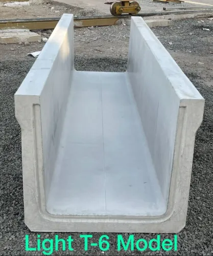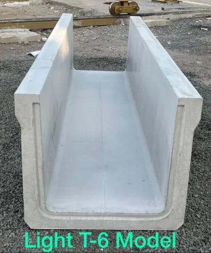
A 150 mm by 200 mm drain is not automatically adequate because its capacity depends on the water it receives, the rainfall design, the available fall and the outlet. By the end, you will be able to check that capacity, set a continuous invert, specify the supporting works and choose covers and joints that remain serviceable after installation.
Key takeaways
- Calculate peak runoff before selecting drain width and depth.
- Confirm the invert line and support every drain section continuously.
- Use joints, covers and access points that suit cleaning and safety needs.
- Match drain strength and cover rating to traffic and installation conditions.
Check the catchment before choosing the drain size
A 150 mm by 200 mm U-shaped channel is suitable only after you compare peak runoff with its U shape precast drain capacity at the available slope. Confirm that these are internal width and depth; wall thickness does not carry water.
Estimate peak inflow with the Rational Method: Q = 0.00278 × C × i × A, where Q is cubic metres per second, C is the runoff coefficient, i is rainfall intensity in millimetres per hour, and A is the catchment area in hectares.
Use the design storm required for your site, not an annual average.
- Map every roof, paved strip, roadside section and yard draining toward the channel.
- Select the rainfall intensity for the chosen storm duration and return period; the duration should reflect the catchment’s time of concentration.
- Calculate channel flow with Manning’s equation, Q = (1/n) × A × R2/3 × S1/2, using the internal wetted area, hydraulic radius, longitudinal slope and concrete roughness.
- Keep freeboard and reduce the calculated capacity for sediment, partial blockage and inlet losses.
| Catchment type | Runoff coefficient to assess | Main check |
|---|---|---|
| Roof | About 0.9–1.0 | Downpipes and inlet spacing |
| Paved roadside | About 0.8–0.95 | Kerb inlets and grate blockage |
| Unpaved yard | About 0.3–0.7 | Compaction, ponding and sediment |
A correct calculation still fails if the outlet causes scour or the invert has steps. Provide suitable inlets, a continuous fall, and an apron, headwall or energy dissipator at discharge.
Set the invert and build a continuously supported drain line
Set the invert level at the outlet first, then transfer it upstream with a laser level, survey instrument or tightly controlled string line. Calculate the longitudinal slope from these fixed points; setting units by eye can create an accumulated rise that traps sediment and interrupts flow.
1. Mark the drain centreline and excavate wide and deep enough for the unit, granular bedding and side support. Remove soft spots from the drain excavation and compact the formation until it provides uniform bearing.
2. Place the granular bedding at the specified thickness and trim it to the design fall. Extend support beneath the full base, not just beneath the edges; point support can crack units and differential settlement can create steps at joints.
3. Lift each U-drain at the manufacturer’s intended points using suitable gear. Check the base, corners, tongues, rebates and bearing surfaces before lowering it into place; do not bury cracked or badly spalled units.
4. Place units in sequence, checking the invert level, line and joint seating after every unit. Remove high spots, concrete nibs and displaced bedding immediately, because a small local step becomes a sediment trap.
5. Haunch the sides where the design requires it, then backfill both sides in balanced layers using approved material. Compact each layer without pushing the unit out of line, and prevent surface water from washing fine material beneath the drain.
Recheck the completed invert before covering the excavation. On steep ground, do not solve excessive velocity by simply deepening or upsizing the channel; use designed drops, check steps or energy dissipation at the approved outlet.
Detail joints, covers and access for safe long-term use
Leakage starts at an unprepared joint, while blockage starts at a joint step or an inaccessible low point. Treat plain-end joints as designed connections: clean the mating faces, confirm the specified gap, and use the specified joint sealant or gasket. Do not assume mortar makes a surface-water drain watertight.
- Use a flexible sealant where the line crosses variable ground, an embankment edge, a utility trench or a rigid-structure interface.
- Tool the sealant continuously around the joint so soil cannot migrate through a pinhole or open edge.
- Remove concrete nibs and excess sealant from the channel before it cures; either obstruction can trap silt and reduce flow.
Install drain covers on level, continuous bearing ledges. A cover that touches at two corners will rock, break its edge or rattle under traffic. Set the frame flush with the finished pavement and prevent a raised rim from creating a trip hazard or an unsafe level change.
Select the cover for the actual wheel-load position and support condition; an A15 pedestrian-rated cover under EN 1433 is not a vehicle cover, and a locally fabricated cover must not claim that class without assessment.
Plan access before closing the line. Provide removable covers at bends, junctions, outlet transitions and known sediment-collection points, then leave enough clearance to lift them safely. Keep the outlet inspectable; a sealed, buried end can turn a small blockage into standing water and joint leakage.
Match the drain and cover to the loading and installation conditions
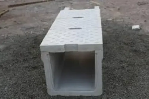
A light-duty covered U-drain is the right choice for pedestrian areas, landscaped edges and service strips where vehicles cannot reach the cover. The cover keeps out litter and prevents foot injuries, but it is not automatically safe for vehicle loading.
Use the installation location—not the drain’s RCC grade—to select the cover. EN 1433 load classes provide a useful reference:
| Option | Typical setting | Decision |
|---|---|---|
| A15 cover | Pedestrian and cycle areas | Suitable where vehicles are excluded |
| B125 or C250 cover | Footways, parking edges and kerbside zones | Use only with verified support and controlled vehicle access |
| D400 cover | Carriageways and delivery routes | Required where road traffic or wheel loads cross the drain |
| E600 or F900 system | Industrial yards, ports and exceptionally heavy loads | Use a tested heavy-duty system, not a locally fabricated plate |
Do not apply an EN 1433 class to an untested local cover. Ask for evidence covering the complete cover, seating frame, bearing width and concrete support; a strong plate can fail when its edges rock or the surrounding pavement settles.
If trucks cross the line, choose a stronger cover or a traffic-rated trench or box-drain system designed for that wheel position. Choose a different drain arrangement when deep backfill, frequent crossings, high impact or weak formation would overload the unit.
Triilok Precast can help you verify the proposed cover and support detail against the actual site access plan.
Related products
 | U Shape Drain Drain Material RCC Internal Width 150 mm Internal Depth 200 mm Length Per Piece 500 mm Load Class Light Duty Cover Type With Cover Reinforcement Type... View product → |
 | Drain Cover Drain Material RCC Internal Width 150 mm Internal Depth 200 mm Length Per Piece 500 mm Load Class Light Duty Cover Type With Cover Reinforcement Type... View product → |
Compare systems by maintenance access, flow control and outlet risk
After installation, a U-shaped precast drain gives you visible flow, predictable dimensions and direct cleaning access, provided the invert has no steps or displaced joints. Its open section makes drain maintenance and sediment removal faster than work inside buried pipes, but leaves, plastic and safety hazards require regular attention.
| Option | Maintenance access | Flow control | Outlet risk |
|---|---|---|---|
| U-shaped precast drain | Open units are easy to inspect and sweep; provide access at bends, junctions, inlet drops, slope changes and outfalls. Covers require lifting or dedicated openings. | Consistent section improves conveyance, but a joint step or concrete nib creates a sediment trap. | Concentrated discharge can scour soil, pavement edges or walls; add an apron, headwall, riprap or energy dissipator. |
| Cast-in-situ concrete | Access remains open, but rough finishing and cracking complicate cleaning. | Shape and fall depend on workmanship, so irregularities reduce reliable flow. | Cracks and poorly formed outlets can erode surrounding soil. |
| Box drain | Larger internal space aids sediment removal, but a cover can make entry difficult. | Handles larger flows when sized correctly, with fewer exposed obstructions. | High outlet velocity still needs outfall erosion control. |
| Covered trench drain | Grates provide cleaning access, but narrow channels clog quickly with debris. | Good surface interception; limited depth reduces storage. | Small outlets concentrate flow and need protection. |
| Pipe | Requires rodding eyes, inspection chambers or jetting equipment for cleaning access. | Smooth, enclosed conveyance hides blockages until capacity is lost. | Outfalls discharge concentrated flow and require scour protection. |
| Earthen channel | Simple to enter and clear, but vegetation and deposited sediment demand frequent work. | Rough, changing sides reduce predictable capacity. | Erosion can widen the channel and move sediment downstream. |
Frequently asked questions
How do you choose the right U-shaped precast drain size?
Check the catchment area, surface runoff, peak flow and available slope before selecting the drain’s internal width and depth. A 150 mm by 200 mm channel is suitable only when its hydraulic capacity exceeds the design flow.
How should you install a continuous U-shaped precast drain line?
Set the invert level before placing sections, prepare a stable foundation and support the full underside of each drain. Check line, level and joint alignment as installation progresses.
What should you consider when detailing drain joints, covers and access?
Seal or detail joints to limit leakage and soil entry, provide covers where people or vehicles cross, and include access points where cleaning and inspection equipment can reach the channel.
How do loading and site conditions affect drain and cover selection?
Select the drain and cover for the expected pedestrian, light-vehicle or heavy-vehicle loading, then account for bedding, backfill, groundwater, slope and installation access.
How can you compare drainage systems beyond initial cost?
Compare cleaning access, flow control, joint performance, cover safety and the risk of erosion or blockage at the outlet, not only the purchase price.