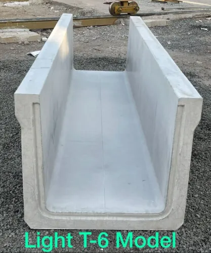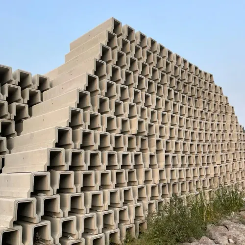
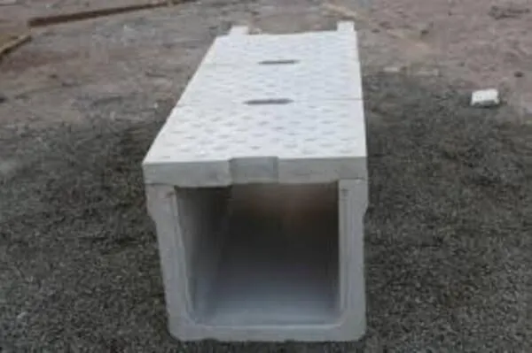
A 150 mm by 200 mm channel is not automatically large enough for a road, driveway or sloping site. You need to test its hydraulic capacity, set a reliable drainage line, build a stable bearing surface and specify covers, joints and outlets for the actual loads and water volumes.
Key takeaways
- Calculate runoff from the full contributing catchment, not the drain alone.
- Set channel gradient, inlets and outlets before excavation begins.
- Compact the trench base and align continuous sections on a firm bed.
- Specify joint details, load-rated covers and crossing reinforcement for traffic.
How do you check whether the channel can carry the design runoff?
Check the contributing catchment before checking the drain. Define the paved road, driveway, roof or slope that sends water to the channel, then obtain the design rainfall intensity for the selected storm duration and return period.
For a small, defined catchment, calculate peak runoff with the Rational Method, Q = C i A. Use runoff coefficient C, rainfall intensity i and area A in consistent units. Then compare that flow with the U shape drain hydraulic capacity at the proposed water depth.
| Check | Calculation | What it prevents |
|---|---|---|
| Catchment runoff | Q = C i A | Underestimating inflow from roads, roofs or slopes |
| Channel capacity | Manning equation: Q = (1/n)AR^(2/3)S^(1/2) | Selecting a section by nominal dimensions alone |
| Operating safety | Freeboard, velocity and boundary shear | Overtopping, scour and joint damage |
In the Manning equation, A is the flowing cross-sectional area, R is the hydraulic radius and S is the longitudinal slope. Recalculate A and R at the actual depth: a 150 mm by 200 mm channel does not have one fixed capacity.
Use n = 0.012–0.015 for aligned, clean, smooth finished concrete. Sediment, vegetation, debris and offset joints increase resistance and reduce capacity. Check freeboard, permissible velocity and boundary shear as well as discharge. A steep grade or concentrated inflow can scour the bed and joints even when the calculated flow fits inside the section.
Where should the gradient, inlets, crossings and outlets go?
Set the drain gradient from a surveyed high point to a controlled outlet, then calculate the resulting velocity and boundary shear. A steep fall can scour the concrete bed, joints or downstream soil even when the U-drain carries the design discharge.
Do not rely on the U-drain alone to collect sheet flow. Set roadside inlet spacing around sag points, road intersections, changes in superelevation, driveway low points and places where a kerb or shoulder directs water toward the channel.
Check inlet capture and bypass flow separately; an adequately sized channel fails when water skips past a blocked or undersized inlet.
Use this setting-out checklist:
- Mark each inlet at the actual low point, not merely at equal distances.
- Provide cross-drain installation where runoff must pass beneath a road, access track or embankment.
- Size the downstream conduit for the same design storm event as the roadside channel.
- Record every inlet, cross-drain, outlet, invert level and flow direction.
- Check the proposed grade against permissible velocity and scour protection requirements.
At the outlet, connect the U-drain to the receiving pipe or drain without creating a smaller downstream throat. Add a headwall, apron, riprap, stilling arrangement or graded transition where discharge could erode soil. Check backwater from the receiving system and keep the outlet above its controlling water level where the site permits.
How do you prepare the trench and install continuous sections?
1. Set out the centreline, finished invert, flow direction and outlet before trench preparation for precast drain installation begins. Mark the design fall so excavation does not force a later reverse slope.
2. Excavate to formation level, remove soft spots and compact the subgrade to the project’s specified density. Do not place units on isolated hard points or loose fill; uneven support can crack the base and open joints after settlement.
3. Install the designed bedding layer. Use compacted granular bedding or concrete bedding as specified, forming a continuous, level surface that supports the full base rather than only its edges. Clean loose material from the bed before placement.
4. Place each 500 mm drain section against the previous unit and check it with a straightedge and level. Run a stringline or laser level across several units, because judging each section by eye can hide a raised joint or reverse fall that traps sediment and holds water.
5. Bring successive plain ends together using the specified mortar, sealant, gasket or other joint treatment. Close gaps that could admit surrounding soil, but remove excess mortar before it forms an internal step; clean bedding and debris from the channel before installing the next section.
6. Compact side backfill in controlled layers and provide lateral restraint where traffic surcharge or soil pressure could move the walls. Reject units with transport cracks, badly chipped ends or distortion unless the manufacturer provides a documented repair method.
How should joints, covers and vehicle crossings be specified?
Specify the joint, cover and crossing as parts of one drainage system, not as finishing details. Open butt joints admit soil, leak collected water and create steps that retain silt. Use plain-end joint sealing with the specified mortar bed, sealant, gasket or other system where watertightness, groundwater exclusion or subgrade protection is required.
- State the joint material, surface preparation, compatible primer, sealant curing time and weather limits.
- Fit each cover on a clean, level bearing edge. Specify the frame, bedding or mechanical restraint that prevents rocking, and confirm that lifting or maintenance cannot shift it.
- Separate pedestrian and verge use from vehicle loading. A cover rated EN 1433 A15 for light-duty pedestrian areas is not automatically suitable beneath car tyres, at a driveway, in a parking area or beside a carriageway shoulder.
- Record the drain cover load class, test method, allowable vehicle wheel loading, support condition and vehicle-access limitation.
- Check the precast U-section, reinforcement, base, bedding, side backfill and lateral restraint for the crossing load. EN 1433 classifies surface drainage channels and their gratings or covers; it does not prove that the concrete U-section can carry traffic.
- Design the crossing for vehicle surcharge as a complete system, including the approach slab or pavement transition and support beneath the unit.
A traffic-rated cover cannot compensate for point bearing, soft ground or a lightly reinforced channel. Require the supplier’s declared support assumptions and reject any specification that names only a cover class without the installed crossing detail.
What should a manufacturer provide before you approve the drainage system?
Approve the system only after receiving a precast drain manufacturer submittal for the complete installed assembly, not a comparison based on internal width alone. A narrow unit with thicker walls, stronger concrete or better support can outperform a wider unit and cost less to install.
1. Require internal width and depth, wall and base thickness, unit length and mass, concrete grade, reinforcement, reinforcement cover, lifting points, dimensional tolerances and joint treatment. The submittal must also state allowable installation surcharge, design slope limits, and assumed bedding and side-support conditions.
2. Request test evidence for the declared cover or grate class. Where vehicles can approach or cross the drain, obtain separate structural information for the U-section, base, reinforcement, bedding and lateral support; a traffic-rated grate does not make a lightly reinforced channel vehicle-safe.
3. Check that mix proportions, curing, crack control and reinforcement cover address IS 456 durability for the site exposure, including wetting and drying, chlorides, sulfates and industrial runoff. Compressive strength alone does not predict service life.
4. Confirm haulage access, lifting capacity, edge protection and delivery inspection. Triilok Precast can support this review with repeatable factory-made units and installation information, but reject chipped or cracked sections unless a documented repair procedure exists.
5. Record drain maintenance at handover: remove sediment and vegetation, inspect joints after settlement, clear narrow crossings and check outlets after heavy storms. Factory consistency reduces site shuttering; transport and handling remain design risks.
Related products
 | U Shape Drain Drain Material RCC Internal Width 150 mm Internal Depth 200 mm Length Per Piece 500 mm Load Class Light Duty Cover Type With Cover Reinforcement Type... View product → |
 | Drain Cover Drain Material RCC Internal Width 150 mm Internal Depth 200 mm Length Per Piece 500 mm Load Class Light Duty Cover Type With Cover Reinforcement Type... View product → |
Frequently asked questions
How do you check whether a U-shaped channel can carry design runoff?
Define the contributing catchment, select the design rainfall intensity and calculate peak runoff before choosing the channel size and slope.
Where should the gradient, inlets, crossings and outlets go?
Set a continuous fall toward a legal discharge point, place inlets at low points, protect crossings, and prevent outlet erosion.
How do you prepare the trench and install continuous precast sections?
Excavate to the design line, compact the formation, place the specified bedding, align each section and seal the joints.
How should joints, covers and vehicle crossings be specified?
Specify the joint sealant, cover dimensions and load class, plus reinforced support details wherever vehicles cross the channel.
What should a manufacturer provide before drainage approval?
Request section dimensions, concrete details, load data, installation instructions, lifting information, tolerances and product traceability documents.