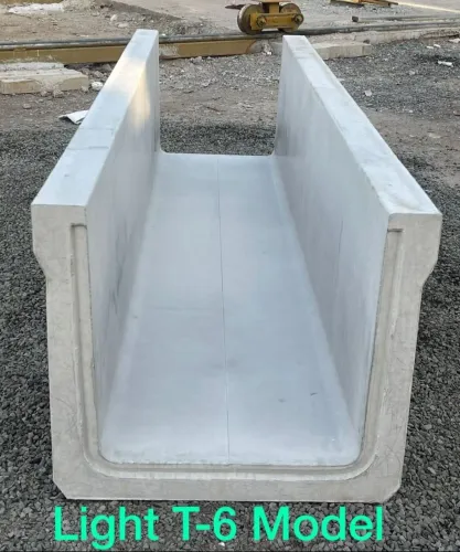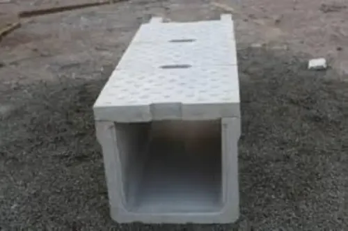
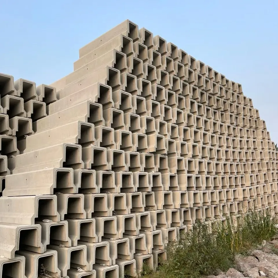
A U shape drain is not suitable simply because its nominal opening matches a drawing or catalogue listing. You need to verify its structural design, hydraulic performance, manufacturing controls, joint treatment, covers, handling requirements and total installed cost before approving a supplier.
Key takeaways
- Specify opening, thickness, reinforcement, tolerances and load requirement first.
- Inspect dimensional accuracy, concrete finish and production-control records.
- Match drain bodies, covers and lifting points to actual site loads.
- Compare excavation, joints, connections, handling and installation—not only metre rates.
Define the Drain Specification Before Comparing Manufacturers
Specify the actual internal width and depth, wall and base thickness, unit length, concrete strength class, reinforcement grade and spacing, joint detail, cover or grate arrangement, allowable dimensional tolerances and governing vehicle-load requirement. “RCC U-drain” is not a sufficient description: two units with the same opening can have different reinforcement, wall thickness and structural capacity.
1. Send the same schedule to every U shape drain manufacturer. Require the concrete grade, reinforcement details, joint gap and sealing method, cover seating arrangement, clear opening, lifting points and tolerances for width, depth, length, squareness and level bearing surfaces.
2. Request a U drain product drawing showing section dimensions, reinforcement details, cover seating dimensions and lifting points. Also request concrete mix information, curing records, load-test results, dimensional inspection reports, batch records, repair records and installation instructions.
3. For road or industrial work, require written design assumptions for soil cover, lateral earth pressure, groundwater, bedding support, surcharge, vehicle loading and differential settlement. A laboratory load test cannot prove that joints will remain closed on discontinuous or poorly supported ground.
4. Require traceability for every delivered unit. The supplier must link its casting date, mix identification, concrete test results, mould designation and inspection record to a unit mark, batch number or delivery document; unrelated certificates provide weak evidence of conformity.
Inspect Production Controls, Dimensions and Concrete Finish
A consistent manufacturer can show repeatable production records, not just one good test piece. Visit the production area or request dated evidence linked to delivered units, covering mould accuracy, vibration, batching, demoulding and curing.
Check sampled units for:
- Internal width and depth, wall thickness, base flatness, end squareness and unit length
- Cover or grate fit, bearing surfaces and joint closure
- Reinforcement position and concrete cover against the approved drawing
Small errors accumulate along a long run. Open joints, hydraulic steps and silt traps follow.
Ask for concrete mix control records showing the batching method, water control, aggregate grading and admixture dosage. A documented curing method—moist curing, controlled steam curing or another defined regime—provides stronger evidence than an isolated compressive-strength certificate.
| Evidence | What it demonstrates | Warning sign |
|---|---|---|
| Dated batch and inspection records linked to unit identification | Production consistency and traceability | Generic certificates with no casting date or batch number |
| Curing logs and demoulding records | Controlled strength development and handling | Early demoulding with no curing record |
| Dimensional and reinforcement checks | Compliance across delivered pieces | One tested sample representing an entire shipment |
Inspect exposed surfaces for continuous honeycombing, open cracks, exposed reinforcement, warped ends and damaged bearing surfaces. Poor curing, early demoulding and inadequate vibration can leave weak arrises and high absorption even when cube strength passes.
Agree on a written defect criterion before delivery. State which repairs are permitted, whether repairs can reduce cover or joint fit, and who approves them. Reject units that fail those criteria.
Match the Body, Cover and Handling System to Site Loads
Classify every location before accepting a supplier’s capacity claim: pedestrian-only, verge, driveway, car park, road crossing, construction-traffic route or repeated heavy-vehicle lane. A light-duty rating does not prove suitability for trucks, rollers, cranes or other construction equipment.
1. Match the vehicle load requirement to separate evidence for the drain body and cover. Request calculations or load-test results stating wheel load, impact, point contact near the slab edge, bearing condition and repeated-loading assumptions. A cover that passes without the body may still fail at its seating.
2. Inspect drain cover safety at the sample unit. Check seating, anti-rocking fit, clear opening, edge support, lifting points and slip-resistant surface. Confirm that braking or turning forces cannot shift the cover into the channel.
3. Ask for the unit mass, lifting-anchor type or lifting-hole detail, rated capacity, sling-angle assumptions and written handling procedure. Reject improvised lifting through reinforcement or thin edges; chipped corners and hidden cracks can occur before installation.
4. Confirm stacking orientation, maximum storage tiers, dunnage, unloading equipment and transport restraints. Check that the reinforcement schedule covers lifting stresses, temporary unsupported spans, corner effects and concentrated loads, not only a uniformly distributed service load. Also document inspection on arrival and responsibility for transport damage.
Check Hydraulic Capacity, Joints and Connections as One System
Determine hydraulic capacity from design discharge, not opening width alone. Calculate flow from catchment area, rainfall intensity, inlet spacing and the drainage network, then use the actual internal width and depth, longitudinal slope, invert levels and roughness in Manning’s equation. Check wetted perimeter, hydraulic radius, flow depth and required freeboard.
A 150 mm by 200 mm opening can fail if its slope is shallow, its invert is high or debris reduces the flow area. Confirm that design flow passes without excessive depth and that the opening remains large enough for rodding, silt removal and visual inspection.
Select a larger or deeper section when freeboard, debris allowance or maintenance access is inadequate.
For plain-end joints, define the intended water and soil behaviour before ordering.
| Joint intent | Required outcome | Key specification |
|---|---|---|
| Soil-tight | Prevent soil and silt entry | Joint gap, alignment tolerance, bearing length and bedding |
| Hydraulically watertight | Prevent leakage and contaminated-water infiltration | Compatible gasket, mortar or sealant, joint movement and installation method |
| Open to infiltration | Permit controlled water entry | Joint opening, filter treatment and protection against soil migration |
Specify bearing length, bedding, joint gap, alignment tolerance, sealant compatibility and movement allowance. Detail transitions at bends, manholes, inlets and outlets.
Check pipe connections, headwalls, end protection, scour control, debris entry and elevation changes. A direct pipe-to-drain connection can create a hydraulic step and erosion point. Inspect the completed run for settlement, leakage, soil ingress, cover misfit and silt-retaining steps.
Compare the Complete Installed System, Not the Per-Metre Rate
Compare installed drainage cost, not the supplier’s headline rate. A cheap unit becomes expensive when covers, end details, bedding or slow installation sit outside the quotation.
Price these items for the same drawing and chainage:
- Straight units, covers or grates, corners and transitions
- Inlets, outlets, headwalls and erosion protection
- Bedding, joint materials and pipe connections
- Lifting equipment, installation time and site labour
- Haul distance, transport and storage
- Breakage allowance, unloading and inspection
| System | Access and repair | Durability, disruption and labour |
|---|---|---|
| U shape drain | Open access; replace individual units | Precast reduces formwork and curing; joints need continuous bedding |
| Cast-in-place channel | Easy to alter before curing; repairs disrupt the pour | Suits irregular alignments; requires formwork, curing and more site labour |
| Rectangular precast drain | Accessible; damaged sections can be replaced | Fast installation, but transport and lifting demand careful planning |
| Pipe | Limited access; repairs require excavation | Protects flow from debris; crossings reduce surface disruption |
| Box culvert | Large access and robust crossing capacity | High lifting and foundation demands; useful under roads |
| Open earth drain | Simple to reshape; easy visual access | Lowest forming cost, but needs more land and recurring maintenance |
For chlorides, sulfates, sewage, de-icing salts or frequent wetting and drying, specify permeability, cementitious materials, reinforcement cover, crack control and joint-material compatibility separately from compressive strength. Include differential settlement and outlet scour in the design.
In a supplier comparison, ask Triilok Precast or any alternative supplier for a drawing-based quotation stating batch traceability, covers, lifting, transport and installation responsibilities. The better offer is the one that controls interfaces, not the one with the lowest nominal metre rate.
Related products
 | U Shape Drain Drain Material RCC Internal Width 150 mm Internal Depth 200 mm Length Per Piece 500 mm Load Class Light Duty Cover Type With Cover Reinforcement Type... View product → |
 | Drain Cover Drain Material RCC Internal Width 150 mm Internal Depth 200 mm Length Per Piece 500 mm Load Class Light Duty Cover Type With Cover Reinforcement Type... View product → |
Frequently asked questions
What specifications should you define before comparing U-shape drain manufacturers?
Define the internal width and depth, wall and base thickness, unit length, concrete strength class, reinforcement grade and spacing, joint detail, cover or grate arrangement, dimensional tolerances and vehicle-load requirement.
How do you inspect the quality of precast U-drain units?
Check production-control records, measured dimensions, concrete finish, visible honeycombing, cracks, chipped edges, reinforcement details and the manufacturer’s process for rejecting defective units.
How should you match a U-drain system to site loads?
Match the drain body and cover or grate to vehicle loading, soil and installation conditions, then confirm lifting points and handling equipment will not damage the units.
What should you compare besides the U-drain price per metre?
Compare excavation, bedding, transport, unloading, lifting, alignment, jointing, outlet connections, covers, backfilling, site access and replacement risk to calculate the complete installed cost.