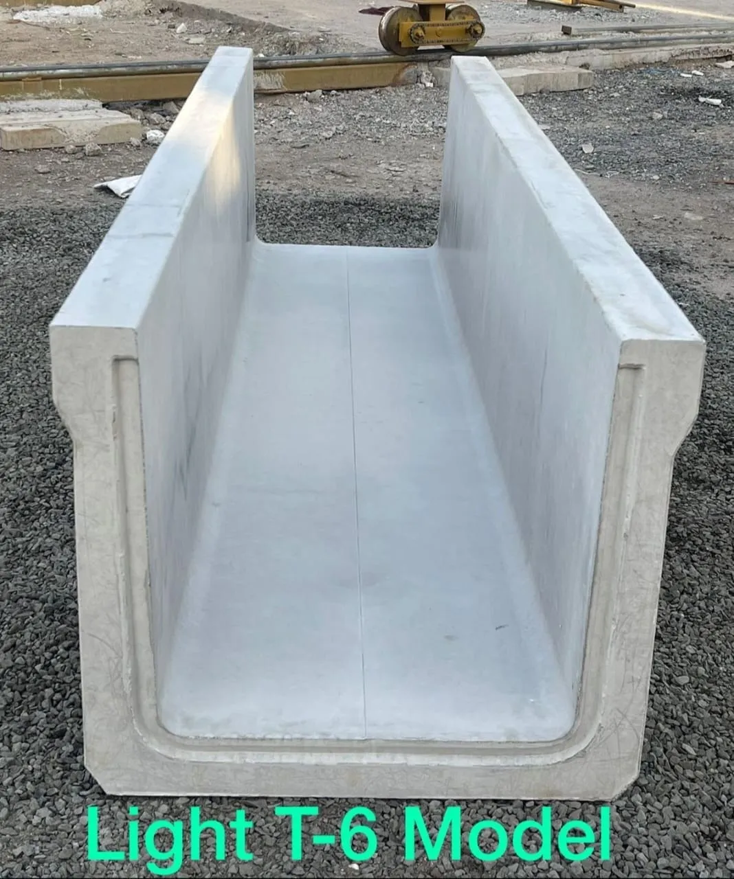
A 150 mm by 200 mm internal channel can carry very different flows depending on the catchment, longitudinal fall, surface roughness, outlet level and sediment load. By the end, you will be able to test its hydraulic suitability, specify the installation geometry, and identify when a different drain system is the safer choice.
Key takeaways
- Size the drain from peak runoff, usable depth, slope and outlet capacity.
- Keep the invert continuous and retain freeboard above the design water level.
- Specify bedding, plain-end joints and cover loads to protect real flow performance.
- Order a U-drain when access, maintenance and discharge conditions suit open channels.
How channel size, slope and runoff determine discharge capacity
U-shaped channel water flow cannot be approved from a 150 mm by 200 mm size alone: you need the runoff peak, usable water depth, longitudinal slope, surface roughness and outlet condition. The 200 mm wall height is not automatically 200 mm of allowable depth; retain freeboard for obstructions and waves.
Estimate design runoff with the Rational Method, Q = C·i·A. Use the contributing area, runoff coefficient C and design rainfall intensity i for the catchment’s time of concentration. If separate surfaces drain to one inlet, calculate their combined peak runoff.
- Measure internal width b and allowable depth y; the hydraulic area b·y, not the external size, enters the calculation.
- Apply the Manning equation: V = (1/n)R^(2/3)S^(1/2), where R = A/P, P = b + 2y, S is slope and n is roughness.
- Compare channel discharge, Q = A·V, with the design runoff while retaining freeboard.
For a 150 mm internal width, use A = 0.15y square metres. Do not substitute 0.20 m unless the design permits water to reach that depth. A steeper slope increases capacity roughly with the square root of slope, but excessive velocity can damage joints and outlets.
Finally, check inlet capacity, abrupt transitions, downstream culverts and tailwater. A straight-channel calculation can still surcharge when the outlet is submerged or downstream water controls the level.
How the invert and gradient keep water moving without causing erosion
The outlet invert must be lower than the inlet invert by the calculated fall; otherwise water will pond, reverse, or surcharge.
Set the longitudinal gradient as the difference between these elevations divided by the drain length, then verify that the resulting velocity is high enough to limit sediment but low enough to protect joints, outlets and receiving ground from erosion.
The manufacturer should state the usable internal dimensions, Manning roughness assumption, allowable slope range and joint tolerance. The installer should transfer the design to a level survey, not estimate the fall from the surrounding surface.
A channel with adequate calculated capacity can still fail when uneven bedding consumes the available gradient or a high downstream invert submerges the outlet.
Use this set-out sequence:
- Establish a benchmark and record the proposed inlet elevation and outlet elevation as invert elevations, not top-of-wall elevations.
- Calculate the outlet invert from the required fall, then check downstream water level, culvert capacity and freeboard.
- Mark intermediate invert levels with a laser level, string line or optical level; check every unit against the line before bedding is fixed.
- Lay units on compacted, continuous bedding so settlement cannot create low spots or reverse grades.
- Keep each joint flush inside the channel. A projecting mortar bead or vertical offset becomes a repeated obstruction.
- On steep falls, specify stepped sections, drop structures, energy dissipation or protected outlet transitions instead of relying on a steeper smooth run.
How channel geometry, bedding and plain-end joints affect real flow
The calculated flow area survives installation only when the installed opening matches the design, the invert remains continuous, and joints do not project into the water.
Specify the internal finished dimensions, not merely the nominal size. Width and depth define usable flow area; wall thickness controls excavation width, unit weight and the support required below each side. Inspect the cured section for excess mortar, chipped corners or a narrowed base.
Support must be continuous. Place units on level, compacted granular bedding where the design permits adjustment, or on a lean concrete foundation where a firm, uniform base is required. Poor compaction creates differential settlement, which forms ponding pockets and sediment traps even when the original calculation is adequate.
Install plain-end units with their inverts and side faces aligned. A small vertical step at every joint becomes a repeated obstruction, increasing turbulence and effective roughness. Use a sealant or mortar suited to water exposure and movement, then finish the internal joint flush; a raised bead reduces the clear area.
Verify the installed geometry at each stage:
- Measure the internal width, depth and invert elevation after placing units.
- Keep joint widths within the approved detail rather than closing gaps by forcing units together.
- Check the outlet connection for a level mismatch, backfall or pipe intrusion.
- Recheck the finished line after backfilling, because compaction beside one unit can lift or tilt it.
A smooth concrete roughness value of n = 0.012–0.015 is not credible if joints are offset, the invert is rough, or sediment remains.
How covers, outlets and maintenance details prevent hydraulic failure
A U-drain should discharge into a catch pit, manhole or downstream channel through an outlet sized for the calculated flow, with its invert aligned to prevent a step, backwater or reverse flow. Do not reduce the outlet abruptly; a smaller pipe can surcharge the channel even when the U-section itself has adequate capacity.
Catch pits and silt traps belong at soil-exposed inlets and before restricted outlet sections. They intercept gravel, leaves and construction debris before material settles in the channel. Provide inspection points at changes in direction, junctions and long runs so a rod or vacuum hose can reach the blockage without breaking covers.
Covers are part of the hydraulic design. A grate can admit water but restrict leaves, while a solid slab removes visible freeboard and can surcharge the drain when blocked or when the downstream system backs up. Keep openings clear and provide safe lifting access for scheduled cleaning.
Specify the cover load classification for its location, such as pedestrian area, driveway or carriageway; never substitute a pedestrian cover on a road crossing. The supporting walls, slab and reinforcement must match wheel loads, soil pressure and buried surcharge.
Added steel does not increase flow capacity, so the manufacturer must state the internal hydraulic dimensions separately from the structural design.
Finish every internal joint flush. A projecting sealant bead or settled unit becomes a repeated obstruction and sediment trap, turning a sound outlet into a maintenance failure.
When a U-drain is the right system—and what to specify before ordering
A precast U-drain outperforms a cast-in-place concrete channel when you need repeatable dimensions, faster placement and immediate access to standard sections. It also gives a cleaner result than an open earth drain, which loses capacity through erosion, weeds and sediment.
A V-drain suits shallow sheet flow; a box drain comparison becomes favourable when you need greater depth, higher loading or a fully covered passage, although box units are usually heavier and harder to install.
The 150 mm by 200 mm light-duty section is unsuitable when the design discharge exceeds its calculated capacity, vehicles or buried surcharge will cross it, the outlet remains submerged, or unprotected soil and gravel can enter it. Do not solve a hydraulic shortfall by adding reinforcement: steel improves handling and structural performance, not flow capacity.
Before ordering, give the manufacturer this information:
- Catchment area, surface type, design storm intensity and calculated peak discharge, including freeboard.
- Surveyed inlet and outlet elevations, available gradient, downstream water level and any culvert restriction.
- Required usable internal width and depth, unit length, joint arrangement and the Manning roughness assumption.
- Loading class: pedestrian, driveway, road traffic or buried surcharge, plus cover requirements.
- Locations for catchpits, silt traps, trash screens and cleaning access before restricted sections.
- Site access, excavation width, bedding details and outlet protection.
Triilok Precast can use this schedule to distinguish a standard light-duty supply from a project-specific RCC section and reinforcement design.
Related products
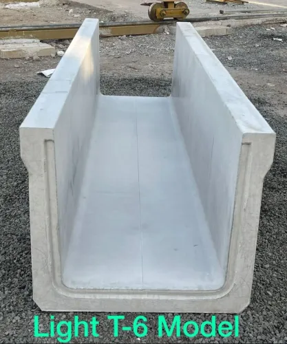
 | U Shape Drain Drain Material RCC Internal Width 150 mm Internal Depth 200 mm Length Per Piece 500 mm Load Class Light Duty Cover Type With Cover Reinforcement Type... View product → |
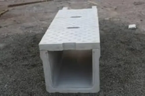
 | Drain Cover Drain Material RCC Internal Width 150 mm Internal Depth 200 mm Length Per Piece 500 mm Load Class Light Duty Cover Type With Cover Reinforcement Type... View product → |
Frequently asked questions
How do channel size, slope and runoff determine U-drain discharge capacity?
Discharge capacity depends on peak runoff, usable water depth, longitudinal slope, channel geometry and surface roughness—not the stated wall size alone. Retain freeboard for obstructions and waves.
Why do the invert and gradient matter in a U-drain?
A continuous invert and controlled gradient keep water moving toward the outlet. Excessive slope or abrupt level changes increase velocity and can cause erosion, scour or joint damage.
How do bedding and plain-end joints affect real water flow?
Level, well-compacted bedding supports the channel and prevents settlement. Plain-end joints must align closely and avoid steps, gaps or projections that trap debris and reduce the hydraulic section.
What covers, outlets and maintenance details prevent hydraulic failure?
Select covers for the expected pedestrian or vehicle load, provide an outlet that can pass the design discharge, and include access points for removing silt, rubbish and vegetation.
When is a U-drain the right drainage system?
A U-drain suits sites needing a defined open channel with inspectable flow and accessible maintenance. Specify runoff, dimensions, slope, freeboard, bedding, joint treatment, cover load and outlet conditions before ordering.